This is the third post in a series where we take a look at EMI and EMC precompliance using real time spectrum analyzers.
Available solutions for radiated emissions testing
Radiated emissions standards exist for commercial, industrial, military, and aerospace products and systems, and involve rigorous testing of RF emissions during device operation. These test systems require sensitive receivers, antennas, and a special test area to approach EMC compliance grade testing, as mentioned in the first article of this series, “What Is EMC/EMI And EMC Precompliance?” . For those developing electronic hardware, low-cost facilities are available for compliance testing products during the development phase. Building a test facility is also possible, but can be tricky due to potential inaccuracies created in the build process, resulting in an out-of-specification test environment. This article briefly highlights a few potential options for development-period RF emissions testing.
Small-scale Test Facilities and Devices
For this article, let’s assume that an anechoic or semi-anechoic chamber is not a feasible option during the development process due to both convenience and cost. During hardware development, there are several less costly and less space demanding options, with the first being an open area test site (OATS). Figure 1 shows an OATS consisting of a device under test separated by 10 meters with a reflective metal flooring material and a wide, non-reflective space around the entire test area. The device under test must have 360 degrees of radiated emissions measurements. EN 55022 and CISPR standards have distance requirements for reflective materials near the test site. In the CISPR standards, this is called the CISPR ellipse and is defined by a major diameter of two times the measurement distance and minor diameter of the square root of three times the measurement distance.
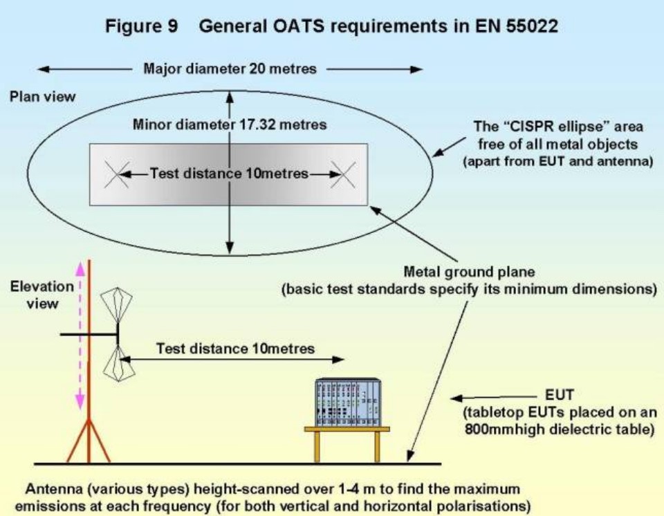
Fig 1 – A basic OATS setup
(Source: http://www.compliance-club.compdfemctestingpart1.pdf)
Other less expensive test options include Gigahertz Transverse Electromagnetic (GTEM), and Transverse Electromagnetic (TEM) cells.
A GTEM cell is a wedge-shaped, compact, semi-anechoic chamber with an integrated stripline antenna used to transmit and receive radiated emissions and immunity tests (see figure 2). Facilities providing GTEM cells can be contracted at lower cost than anechoic chambers, and even OATS.
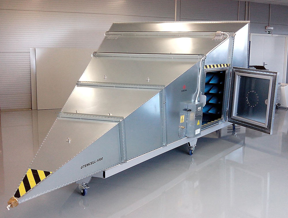
Fig 2 – A GTEM cell is typically constructed from metallic and absorptive materials and standard bulkhead connectors. (Source: https://en.wikipedia.org/wiki/GTEM_cell#/media/File:GTEM1000_-_Ceca_Rep.jpg. License: https://creativecommons.org/licenses/by-sa/4.0/)
If your hardware-in-development is physically smaller in size, TEM cells can be purchased at feasible prices for testing in your own facility, and can even be built at low cost. For PCBs and small electronics, GTEM and TEM cells can often be an affordable and effective means of collecting emissions data on your hardware. However, as EMC compliance standards dictate different test setups, the results could be different than what final EMC testing will produce. For product development and quality assurance purposes, though, these solutions may be adequate.
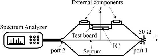
Fig 3 – A TEM cell can be inexpensively created from sheets of metal, an RF load, and an RF connector.
Using a real-time spectrum analyzer during radiated emissions testing can reveal the emissions behavior of a device with more clarity than some EMC labs. RTSAs will measure short duration and intermittent events that EMC testing may not reveal. The compliance testing will require a precise EMC compliant receiver, as an RTSA can be used to test and track emissions behavior, revealing insight into the time-varying details of the emissions.
For this type of testing, the importance of a proper antenna configuration cannot be understated. For radiated emissions testing the antenna needs to be calibrated and each test needs to be corrected for the antenna’s frequency inaccuracies. In EMC test suites, including Signal Hound’s Spike software, the EMC test modules should have properly configured antenna calibration tables, known as antenna factor tables.
Conducted Emissions and Conducted Immunity EMC Precompliance with Current Clamps
Current clamps (also known as current probes or current monitors) can be used to estimate the far field emissions of signals generated by the common mode currents on external cabling. High accuracy far field measurements can be derived, and standards such as CISPR 14, require the use of current probes up to 1000 MHz.
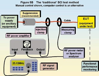
Fig 4 – Bulk Current Injection (BCI) is a method of immunity testing popular in military, aerospace, and automotive industries to evaluate overall assembly or platform compliance.
(Source: http://www.compliance-club.com/archive/old_archive/011021.htm)
Professionally manufactured current clamps can be purchased on a limited budget. However, with a few spare parts, a current clamp that performs adequately for prototyping purposes can be manufactured with limited skill. For EMC precompliance measurements above 200 MHz, PCB traces and device features become effective enough radiators that measurements in the far field are required to ensure that the total emissions are below standards limits.

Fig 5 – DIY current probes constructed of spare wire, split ferrite chokes, and BNC connectors. Source: EDN.COM
As there may be a wide variety of spurious and intermittent signals coupled into (or out of) an electronic device, current clamps connected to an RTSA can be very helpful in analyzing and understanding the sources of these conducted emissions and conducted interference. With devices that have several external cables, multiple RTSAs attached to current clamps can be used to monitor the cables and gauge the impact of immunity signals simultaneously. This ability is enhanced when considering the recording abilities of some RTSAs when analyzing complex device performance alongside conducted immunity and conducted emissions testing.
Magnetic and Electric Probes to Estimate E-Fields
If a frequency sweep produces far field measurements that exceed EMC compliance standards, the radiating features of a design will need to be redesigned for lower emissions. It may be challenging through analysis with voltage and current contact probes to discover the exact source of the emissions. Fortunately, there are accurate devices, such as EMC near-field probes, that can be used to manually scan a PCB or system for the source of the emissions.
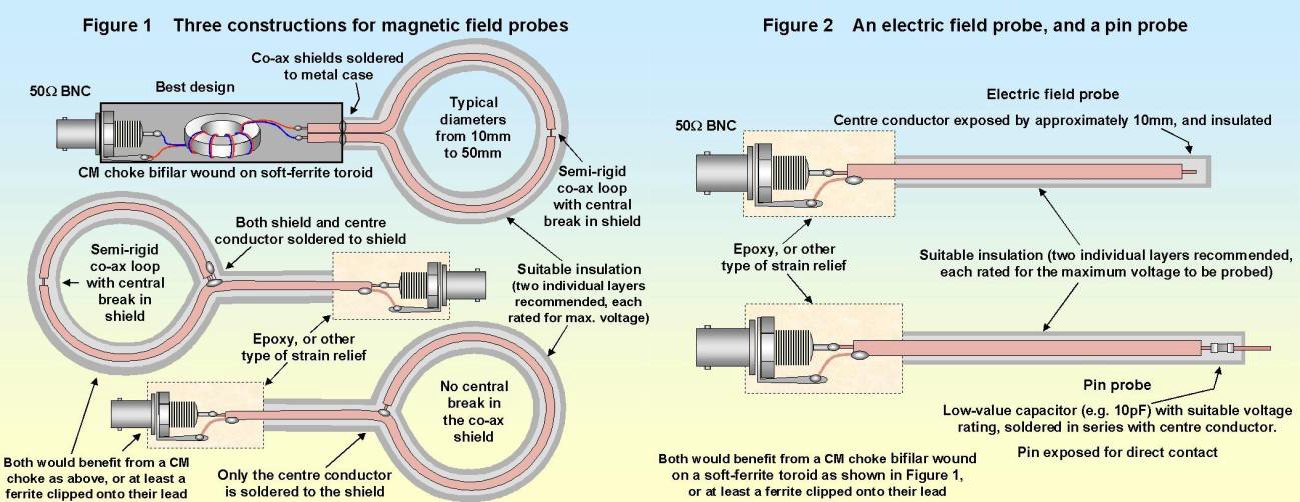
Fig 6 – BNC connectors are used in many DIY test equipment applications below 2 GHz, as BNC connectors are low-cost, easily modified, and robust enough for non-expert hand fabrication.
Conveniently, a small-format PC-driven RTSA can be directly connected to an EMC near-field probe with a portable computer or laptop displaying and processing the results of the EMC probe testing. This combination enables low noise and loss measurements, as the probes are directly connected to the RTSA. This test assembly can be used to inspect the fine features of a PCB by following complex interconnect paths and board features without having to rely on long expensive cabling or equipment carts.
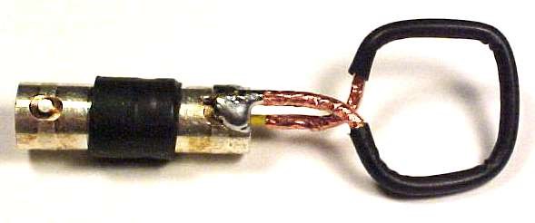
Fig 7 – A DIY current loop probe made with a BNC connector, copper foil, solid copper wire, and heat shrink.
(Source: http://www.emcesd.com/tt120100.htm)
A near-field (NF) probe measurement will not provide a reading that can be directly translated to a far-field measurement. But, the far-field response can be estimated by mathematically converting the near-field response to far-field. Possibly easier, would be making design changes to the device based on the NF test insights and repeat the far-field measurements to confirm that the previous emissions source was reduced. Depending on resources, NF magnetic and electric field probes can be constructed from standards parts and components at low-cost and low-labor, or can be purchased for higher quality measurement requirements.
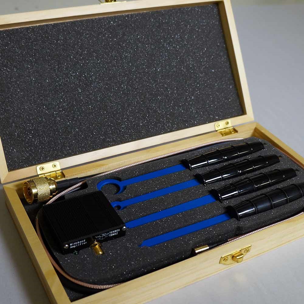
Figure 8 – A commercial set of near-field probes with a wideband amplifier
A variety of options for RF emissions testing
It is true that the requirements for the successful passing of a radiated emissions test are stringent, but these requirements are important. The safety of the user is always a priority when bringing a new product to market and the expectations set forth by government entities are in place to ensure the user’s safety. A variety of RF emissions testing options are available at a range of costs, enabling hardware manufacturers of all sizes to safely and effectively bring their products to market as affordably as possible.
Note—Be sure to read the other posts in this EMC-related series, EMC Precompliance with a Real Time Spectrum Analyzer Part 1 — What Is EMC/EMI And EMC Precompliance?, and EMC Precompliance with a Real Time Spectrum Analyzer Part 2 — How PC-Driven USB RTSAs Enable Low-Cost And Efficient EMC Precompliance.
References
www.tek.com/dl/37W_22084_1_MR_Letter.pdf
www.tek.com/dl/37A_60141_1_HR_Letter.pdf
https://www.rohde-schwarz.com/vn/applications/comparison-of-time-domain-scans-and-stepped-frequency-scans-in-emi-test-receivers-application-note_56280-54019.html
http://literature.cdn.keysight.com/litweb/pdf/5989-6899EN.pdf?id=1203888
http://cp.literature.agilent.com/litweb/pdf/5968-3661E.pdf
http://www.keysight.com/main/eventDetail.jspx?cc=US&lc=eng&ckey=2462479&nid=-35261.685629.08&pid=1147919
http://www.emcfastpass.com/pre-compliance-testing-guide/
http://www.feebel.be/en/system/files/FEE%20131016%20EMC%20Diagnostics_0.pdf
http://www.testforce.com/testforce_files/Practical_EMI_Measurements.pdf
http://www.emcfastpass.com/wp-content/uploads/2015/04/Getting_EMC_Right_First_Time_Intro.pdf
https://signalhound.com/support/forums/topic/bb60-for-emc/
http://www.edn.com/electronics-blogs/the-emc-blog/4429621/Using-current-probes-to-estimate-E-fields
http://incompliancemag.com/article/lessons-learned-from-the-design-and-construction-of-an-open-area-test-site-oats-and-sound-measurement-building/
http://www.emcs.org/acstrial/newsletters/summer08/pp2.pdf
http://www.hottconsultants.com/techtips/tips-cm.html
http://www.emcfastpass.com/top-emc-failures-and-tips-from-5-emc-consultants/
http://www.emcfastpass.com/avoid-the-most-common-failures-with-these-7-essential-emc-design-rules/
http://www.emcfastpass.com/emc-design-review/
http://www.emcfastpass.com/emc-test-equipment-guide/
http://www.emcfastpass.com/emc-testing-beginners-guide/
https://www.ieee.li/pdf/viewgraphs/emc_design_fundamentals.pdf
http://www.eevblog.com/forum/reviews/near-field-probes/
http://www.emcesd.com/tt120100.htm
http://www.compliance-club.com/pdf/emctestingpart1.pdf
http://cas.web.cern.ch/cas/Denmark-2010/Caspers/EMC%20application%20note%202%20Agilent%20CAS2010.pdf
