This is the first post in a series where we take a look at EMI and EMC precompliance using real time spectrum analyzers.
Virtually every electronic device, and many non-electronic and natural phenomenon, produce electromagnetic radiation. This radiation can, intentionally or otherwise, interfere with proper electronics operation—electromagnetic interference (EMI). Electromagnetic compatibility (EMC) is the study of the emissions and susceptibility of electronics generating and properly operating while receiving interference. In order to maintain a level of harmony amongst the myriad of electronic services that define and dominate our modern world, EMC compliance is enforced by national and international organizations and standards.
Additionally, there are many rigorous military and aerospace standards and criteria for EMC emissions and susceptibility that must be met prior to deploying electronics in defense, aeronautics, and space environments. Public safety and emergency responders have similarly strict requirements for reliable and rugged communications devices and electronics. Hence, for any manufacturer, assembler, or designer of electronics, wireless or wired, understanding the stringent necessities of commercial, industrial, and military EMC compliance can help avoid expensive and possibly fatal product failures and recalls.
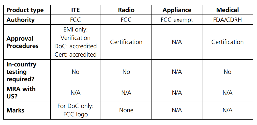
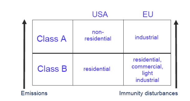
For the different classes of electronics, in the United States and other countries, the standards organizations and type of approval varies (Source: https://www.ieee.li/pdf/essay/guide_to_global_emc_requirements_2007.pdf)
The requirements for electronics operation are enforced in the US by the Federal Communications Commission, and in Europe, by the Conformité Européene (CE). All electronics are required to be certified by these organizations prior to being sold or operated in those regions of the world. Enforcement can take the form of heavy fines, or even legally banning the operation or sale of certain devices. As FCC and CE certified EMC compliance testing is an expensive and challenging task, many manufacturers of electronics prefer to conduct EMC precompliance prior to facing costly design changes during or after EMC compliance testing.
Fortunately, the testing electronics and software necessary to perform EMC precompliance testing are much less costly and challenging to use than in previous decades. So much so, that many companies build do-it-yourself EMC precompliance test systems using a variety of different test figures, housing, and equipment. This may help meet traditional standards of quality, however, the shrinking design cycles, the proliferation of small electronics startups, and cost-effective PC-driven test instruments are creating an exciting ecosystem of DIY that is helping bring products to market in dramatically shortened production cycles.
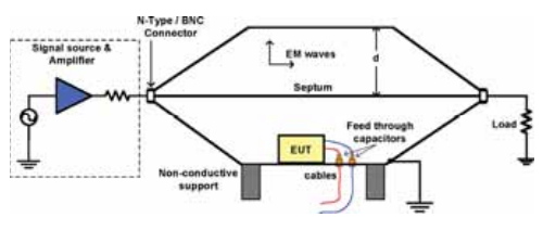
A DIY transverse electromagnetic (TEM) cell used in EMI/EMC precompliance testing can be fabricated without precision equipment or materials for relatively low costs.
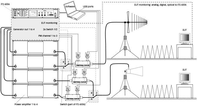
EMC precompliance testing attempts to duplicate—as best as the costs, effort, and expertise allow—EMC compliance testing. Generally, there are two main forms of EMC compliance testing, immunity tests and emissions tests. Immunity tests gauge a product’s susceptibility to damage and improper operation to a wide variety of electrical disturbances and interference. To accomplish this, immunity tests require a RF signal source, RF power amplifier, RF receiver/power meter, electrostatic discharge (ESD) generator, electrical burst generators, surge generator, and method of applying that closely mimic the requirements set in the US, EU, or other country standards. In some immunity testing, a spectrum analyzer can be used to confirm proper operation and calibration of the test equipment and post-testing confirmation of proper device-under-test (DUT) performance.
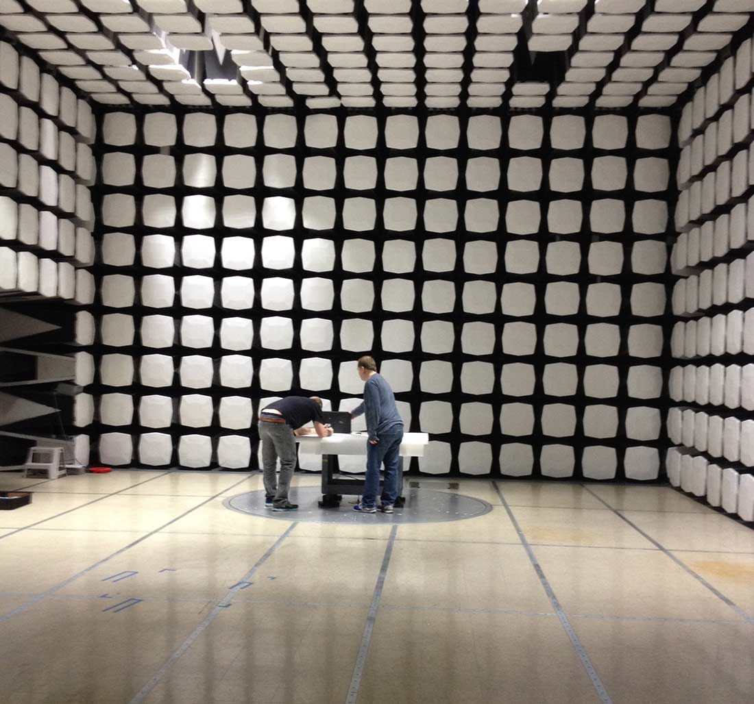
Emissions tests evaluate the electromagnetic radiation given off by a device either through unintended emissions or through emissions generated by energy conducted on accessory cords—power, data, AC, DC, or other cablings— attached to the device. Radiated emissions testing is done using far-field antenna-based measurements in open area test sites, semi-anechoic chambers, a gigahertz transverse electromagnetic cell (GTEM), or a transverse electromagnetic cell (TEM) and an EMC compliance receiver. For devices, such as PCBs and small electronics, near-field electric and magnetic probes may be used instead to estimate the far field behavior, or as a tool to track down the source of radiated emissions and a way to relatively gauge the benefits of design strategies to reduce radiated emissions.
Setting Up a Signal Hound for EMC Testing
Though not necessarily good for absolute measurements, RF signal generators and spectrum analyzers with probes can be used in place of dedicated EMC precompliance test sets and antennas for development and quality assurance purposes. If there is an adequate understanding of the EMC compliance requirements and how to configure the generic test equipment to provide EMC Compliance-like tests, a device design or device production system can be enhanced and improved to avoid potential future EMC Compliance failures.
Going with this approach early on in a design can enable rapid design and redesign cycles that account for EMC compliance during the feedback process. Nevertheless, the measurements provided with generic test equipment won’t necessarily be able to exactly mimic a real EMC compliance signal source or receiver behavior. These factors may require cost-benefit analysis on the risks associated with designing in enough headroom to pass unofficial EMC compliance grade testing and what extra costs and design compromises are necessary.
For example, a required EMC compliance power detector, known as a quasi-peak detector, is specified in the standards for compliance. A dedicated EMC precompliance test set may have an analog quasi-peak detector circuit that is swept through the standards frequencies of interest referencing the appropriate pass/fail criteria. Without such a device, a spectrum analyzer can be used with the understanding that the peak amplitude in dBV will always be greater than the quasi-peak detector amplitude. The results of a sweep could then be manually compared against the pass/fail criteria. However, if you are enterprising, like Signal Hound’s engineers, you can implement a digital quasi-peak detector in software that processes data from an FFT-based spectrum analyzer.
Further Reading
Check out the extensive list of links below for a variety of EMC-related information. From application theory and processes to rules, regulations, and questions, you’ll find a wide variety of valuable material from around the web.
References
- www.tek.com/dl/37W_22084_1_MR_Letter.pdf
- www.tek.com/dl/37A_60141_1_HR_Letter.pdf
- https://www.rohde-schwarz.com/vn/applications/comparison-of-time-domain-scans-and-stepped-frequency-scans-in-emi-test-receivers-application-note_56280-54019.html
- http://literature.cdn.keysight.com/litweb/pdf/5989-6899EN.pdf?id=1203888
- http://cp.literature.agilent.com/litweb/pdf/5968-3661E.pdf
- http://www.keysight.com/main/eventDetail.jspx?cc=US&lc=eng&ckey=2462479&nid=-35261.685629.08&pid=1147919
- http://www.emcfastpass.com/pre-compliance-testing-guide/
- http://www.feebel.be/en/system/files/FEE%20131016%20EMC%20Diagnostics_0.pdf
- http://www.testforce.com/testforce_files/Practical_EMI_Measurements.pdf
- http://www.emcfastpass.com/wp-content/uploads/2015/04/Getting_EMC_Right_First_Time_Intro.pdf
- https://signalhound.com/support/forums/topic/bb60-for-emc/
- http://www.edn.com/electronics-blogs/the-emc-blog/4429621/Using-current-probes-to-estimate-E-fields
- http://incompliancemag.com/article/lessons-learned-from-the-design-and-construction-of-an-open-area-test-site-oats-and-sound-measurement-building/
- http://www.emcs.org/acstrial/newsletters/summer08/pp2.pdf
- http://www.hottconsultants.com/techtips/tips-cm.html
- http://www.emcfastpass.com/top-emc-failures-and-tips-from-5-emc-consultants/
- http://www.emcfastpass.com/avoid-the-most-common-failures-with-these-7-essential-emc-design-rules/
- http://www.emcfastpass.com/emc-design-review/
- http://www.emcfastpass.com/emc-test-equipment-guide/
- http://www.emcfastpass.com/emc-testing-beginners-guide/
- https://www.ieee.li/pdf/viewgraphs/emc_design_fundamentals.pdf
- https://www.ieee.li/pdf/essay/guide_to_global_emc_requirements_2007.pdf
