Why Multipath Interference?
In RF communications, understanding multipath interference is critical to understanding wireless communications in an urban environment. Generally, multipath propagation leads to undesired effects, such as fading. Recent advances in multiple input, multiple output (MIMO) technology have actually exploited multipath interference to significantly increase bandwidth. Because of these new technologies, it is more important than ever that RF engineering students understand this effect.
An effective hands-on classroom demonstration of multipath constructive and destructive interference can be achieved with a Signal Hound VSG25A vector signal generator, BB60C spectrum analyzer, and two ISM-band antennas. The $495 VSG25A will be used to generate hundreds of tones simultaneously across the entire and of interest, and the BB60C will be used to display the amplitude of these tones, giving you around 30 frames per second of path loss information.

Spike software showing multipath Interference using the VSG25A and BB60C
It is important that the laws regarding RF transmitters be reviewed before conducting this experiment, as you will be attaching a signal generator to an antenna. In general, use the minimum transmit power required for an effective demonstration (e.g. -10 dBm). Disable the RF output and disconnect the transmitter from the antenna immediately after the demonstration.
How to Perform This Demonstration
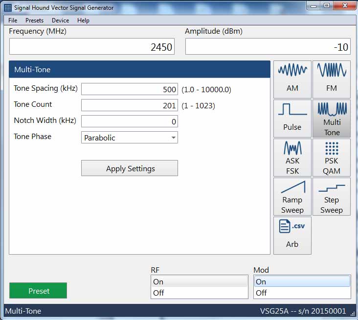
With the VSG25A usb-powered vector signal generator connected to a PC, start the VSG’s software and set the VSG25A to generate evenly spaced tones across up to 100 MHz of spectrum.
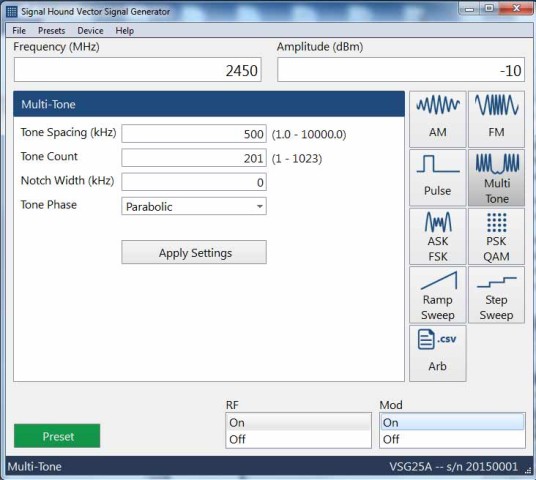
Generating tones across 100 MHz of spectrum
Using Signal Hound’s Spike spectrum analyzer software, set the BB60C to sweep this same spectrum with a 10 kHz RBW. Set your reference level to the lowest value that will not result in clipping (e.g. -40 dBm).
Position the antennas perhaps 10 feet apart. Connect the antennas to the BB60C and VSG25A. Watch the signal levels as objects or people move around the antennas, or as the antennas themselves are moved. It doesn’t take much to see dramatic changes in the path loss!
See the demo in action here:
