|
SM API
|
|
SM API
|
This documentation is a reference for the Signal Hound SM200 and SM435 (SM) spectrum analyzer programming interface (API). The API provides a set of C functions for making measurements with the SM devices. The API is C ABI compatible making is possible to be interfaced from most programming languages.
All code examples are located in the examples/ folder in the SDK which can be downloaded at www.signalhound.com/software-development-kit.
This section covers the main measurements available through the API.
Also see Basic API Usage for more information.
Versions are of the form major.minor.revision.
A major change signifies a significant change in functionality relating to one or more measurements, or the addition of significant functionality. Function prototypes have likely changed.
A minor change signifies additions that may improve existing functionality or fix major bugs but make no changes that might affect existing user’s measurements. Function prototypes can change but do not change existing parameters meanings.
A revision change signifies minor changes or bug fixes. Function prototypes will not change. Users should be able to update by simply replacing the .DLL/.so.
See the 10GbE network configuration guide for setting up a 10GbE network for SM200C/SM435C operation.
There are two ways to set the sensitivity of the receiver, through the attenuator or the reference level. (smSetAttenuator/smSetRefLevel) The smSetAttenuator function allows direct control of the sensitivity. If the attenuator is set to auto, then the API chooses the best attenuator value based on the reference level selected. The attenuator is set to auto by default.
The reference level setting will automatically adjust the sensitivity to have the most dynamic range for signals at or near (~5dB) below the reference level. If you know the expected input signal level of your signal, setting the reference level to 5dB above your expected input will provide the most dynamic range. Using the reference level, you can also ensure the receiver does not experience an ADC overload by setting a reference level well above input signal level ranges.
The reference level parameter is the suggested method of controlling the receiver sensitivity.
The internal GPS communicates to the API on initialization, during all active measurements, and when requested through the smGetGPSInfo function. It does not perform active communication to the PC at any time other than these.
NMEA sentences are updated once per second and timestamps are updated every time the GPS has a chance to communicate with the PC. This means, several consecutive sweeps within a 1 second frame have the chance to update the NMEA information at most once, and a provide a new timestamp for each sweep.
The GPS will automatically lock with no external assistance. You can query the state of the GPS lock with either the smGetGPSState function, or by examining the return status of smGetGPSInfo. From a cold start, expect a lock within the first few minutes. A warm or hot start should see a lock much quicker.
When the GPS is locked, I/Q data and sweep timestamping occurs using the internal GPS PPS signal and NMEA information. Once GPS lock is achieved, GPS timestamping occurs immediately and required no user intervention. Until the GPS is locked, timestamping occurs with the system clock, which has a typical accuracy of +/- 16ms.
If the GPS loses lock, the timestamps will advance at the nominal rate until the GPS achieves lock again. Off GPS lock timestamps will be coherent between measurement reconfigurations until the device is closed through the API or the device loses power.
The system GPS can be in one of three states,
The current GPS state can be queried with smGetGPSState. If the device is actively making measurements the recommended way to wait for lock/discipline is by querying the GPS state after each measurement. If the device is idle (after an smAbort) the recommended method is to query the GPS state in a busy loop, preferably with a small wait between queries, something like 1 second is adequate. (careful! it may never break out of a loop if you break on lock detect and the SM cannot achieve it)
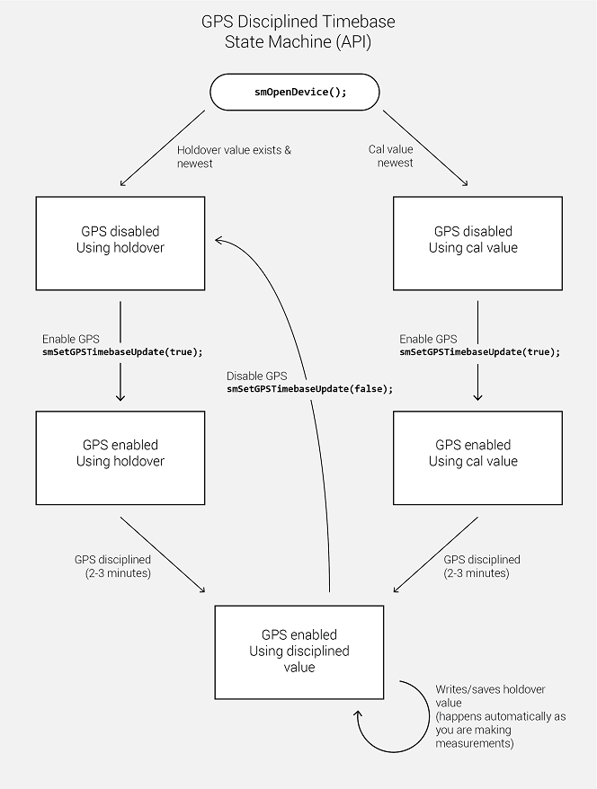
The GPS will lock automatically with a GPS antenna attached, but for the GPS to discipline the SM, it must first be enabled. To enable GPS disciplining, use the smSetGPSTimebaseUpdate function. Below is the state machine for GPS disciplining. To summarize, the timebase is adjusted by the newer of the two correction factors, either the last GPS holdover value or the last Signal Hound calibration value. Only after enabling the GPS disciplining will the SM utilize a GPS lock to discipline the SM and store holdover values.
Using the API, customers can write custom messages to the internal u-blox M8 GPS receiver. The user can also retrieve responses to these messages. The two functions that enable this are smWriteToGPS (writing) and smGetGPSInfo (reading). See these functions for more information.
This functionality is only available on receivers with the following firmware versions or newer.
SM200A: 4.5.10, SM200B: 4.5.13, SM200C: 6.6.4, SM435B: All, SM435C: All
Devices with this functionality will be referred to as devices with “GPS write” functionality in this document.
All messages sent to the GPS are sent over port 4 (SPI). This is the only port the customer has access to. UBX and NMEA messages can be sent. All messages are documented in the u-blox M8 GPS manual. Messages must match the frame structure documented in the u-blox manual. For example, to send a UBX message, the sync chars, class, ID, length, payload (if present), and 2-byte checksum must all be present and in the correct order in the provided message.
An example message for a “Get” UBX-CFG-NAV5 msg with empty payload is
msg[8] = {0xB5, 0x62, 0x06, 0x24, 0x0, 0x0, 0x2A, 0x84};
Responses are returned with the NMEA sentences through the smGetGPSInfo function. Responses must be parsed by the customer and can appear anywhere in the NMEA response buffer, including being split between buffers (rare).
To retrieve a response, call smGetGPSInfo with an adequately sized nmea buffer until the updated parameter is set to true, then parse the response for your message. The device must be GPS locked to retrieve a response message, although it is not necessary to have GPS lock to send messages.
See the SM C++ examples for a full example of sending and retrieving UBX messages.
A link to the u-blox M8 manual and protocol specification is below.
On the front panel of the SM there is a DB15 port which provides up to 8 digital logic lines available for immediate read inputs, or output lines as immediate write pins, or configurable through the API to be able to switch during sweeps and I/Q streaming.
Primary use cases for GPIO pins might be controlling an antenna assembly (switching between antennas) or interfacing attenuators.
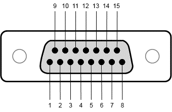
Pinout
| Pin | Description | Pin | Description |
|---|---|---|---|
| 1 | GPIO(0) | 9 | GPIO(1) |
| 2 | GPIO(2) | 10 | GPIO(3) |
| 3 | Vdd in (1.8 to 3.3V) | 11 | 3.3V out (max 30 mA) |
| 4 | GND | 12 | SPI SCLK |
| 5 | SPI MOSI | 13 | SPI MISO |
| 6 | SPI Select | 14 | GPIO(4) |
| 7 | GPIO(5) | 15 | GPIO(6) |
| 8 | GPIO(7) | Shell | GND |
GPIO pins are grouped into two nibbles (4-bits), GPIO pins [0,1,2,3] and GPIO pins [4,5,6,7]. Each nibble can be set to either read or write pins using the smSetGPIOState function. You can read or write pins using the smWriteGPIOImm or smReadGPIOImm functions. These functions can only be called when the device is in an idle state.
Additionally, there are two high speed pin switching modes that you can take advantage of. See the GPIO Sweeps and GPIO Switching (I/Q Streaming) sections for more information.
See the C++ code examples for using the set/get immediate functions.
GPIO can utilized in 2 ways with sweeps, inter-sweep, and intra-sweep. Inter-sweep GPIO changes occur in between sweeps. This can be used to change the GPIO up to a maximum of once per sweep. Intra-sweep GPIO changes occur during sweeps and is used to change the GPIO at fixed frequencies during a sweep.
Inter-sweep GPIO switching allows for rapidly sweeping a frequency range and modifying the GPIO pins for each sweep.
Inter-sweep GPIO changes are supported with the fast sweep speed and queued sweeps only. Using the smSetSweepGPIO function you can associate a GPIO setting with a given sweep. When the sweep is started the GPIO is changed just prior to the sweep occurring. There is ~20 microseconds between the GPIO change and the sweep starting.
If inter-sweep GPIO changes are needed with normal sweep speed, avoid queued sweeps and write new GPIO settings using the smWriteGPIOImm function in between sweeps.
See the smSetSweepGPIO function description and code examples for more information.
The GPIO output pins can be configured to automatically update as the device sweeps across a specified frequency range. As the device sweeps across frequency and crosses user defined frequency boundaries, the GPIO can output specific values. The frequency boundaries and GPIO output settings are configured with smSetGPIOSweep.
This functionality is useful for controlling an antenna assembly while very quickly sweeping a large frequency range. For instance, using the GPIO to switch between different antennas to be used for different frequencies as the SM sweeps the configured span. This would be much faster than individually sweeping each antenna manually.
Due to the digital nature of the SM device, there is a limit on the resolution on which the GPIO can change for GPIO sweeps. In normal sweep mode, the SM is processing spectrum in 39.0625MHz LO steps. This means the frequency resolution at which the GPIO can switch is 39.0625MHz. In fast sweep mode, the LO step size and GPIO switch resolution is increased to 156.25MHz.
This means the GPIO will not switch at the precise frequency you provide. The API is deterministic in choosing which frequencies to switch at, meaning, the same configuration will result in the same GPIO switch frequencies.
The API does not output or provide the actual frequencies the device switched the GPIO at. Signal Hound recommends experimenting with your setup until you find an adequate configuration.
The GPIO output pins can be configured to automatically switch at specific time intervals when the device is in I/Q streaming mode. In this mode, the user can configure a series of GPIO states to be output while the device is streaming I/Q data. This mode is useful for controlling antennas for DF and pseudo-doppler DF systems.
Up to 64 states with customizable dwell times can be configured. Dwell times can be set to a minimum of 40ns and incremented in 20ns steps. For example, a 4 antenna DF system might require a configuration like
| State | GPIO Output | Dwell time (in 20ns ticks) |
|---|---|---|
| 0 | 0x00 | 125,000 |
| 1 | 0x01 | 125,000 |
| 2 | 0x02 | 125,000 |
| 3 | 0x03 | 125,000 |
The configuration above configures the GPIO to switch between 4 states and dwell at each state for 2.5ms each. For a 4 antenna DF system, this configuration will cycle through all the antennas at 100Hz (10ms per revolution).
When I/Q GPIO switching is activated, the external trigger input port is disabled, and internal triggers are generated and provided in the I/Q data stream to indicate when the GPIO state has reached state zero. Triggers generated on the external trigger input port are discarded. Once GPIO switching is disable, the external trigger input is enabled again.
For more information about configuration see smSetGPIOSwitching and smSetGPIOSwitchingDisabled.
Through the front panel DB15 port the SM provides a SPI output interface. (SPI reads are not implemented, only SPI writes, See GPIO for the pinout) The SPI interface can be operated as output only, with a clock rate of 5.2Mbps. Between 1-4 bytes may be output through the SPI interface. Only immediate writes are available. (Direct writes while the device is idling)
The clock line idles high, and data transitions on the falling edge of the clock. It can be used to write to most SPI devices where data is latched on the rising edge of the clock.
See the C++ examples for an example of using the SPI interface.
The SM435 can be configured with the IF output option. When this option is present, the SM435 device can function as a mmWave downconverter from 24-43.5GHz (configurable) and outputting it on the 10MHz output port at 1.5GHz center frequency (not configurable). Detailed specifications can be found in the SM product manual.
When the IF output option is present, the maximum frequency of the device is limited to 40.8GHz instead of 44GHz. The user is responsible for querying for the presence of the IF output option with the smHasIFOutput function and limiting the upper frequency accordingly. An IF output option device can be safely tuned above 40.8GHz without risk of damage but will not properly detect signals above this frequency.
The IF output can be enabled with the smSetIFOutput function. No other measurements can be active while the downconverter is active.
Both smSetAttenuator and smSetRefLevel can be used to control the leveling of the receiver.
The SM has 2 power states, on and standby. The device can be set to standby to save power either when the active measurement mode is idle or sweep mode (assuming no sweeps are currently active).
A short description of each power state is described below.
The SM API is not thread safe. A multi-threaded application is free to call the API from any number of threads if the function calls are synchronized (i.e. using a mutex). Not synchronizing your function calls will lead to undefined behavior.
The API can manage multiple devices within one process. In each process the API manages a list of open devices to prevent a process from opening a device more than once. You may open multiple devices by specifying the serial number of the device directly or allowing the API to discover them automatically.
If you wish to use the API in multiple processes, it is the user’s responsibility to manage a list of devices to prevent the possibility of opening a device twice from two different processes. Two processes communicating to the same device will result in undefined behavior. One possible way to manage inter-process information is to use a named mutex on a Windows system.
If you wish to interface multiple devices on Linux, see the Linux Notes.
By default, Linux applications cannot increase the priority of individual threads unless ran with elevated privilege (root). On Windows this issue does not exist, and the API will elevate the USB data acquisition threads to a higher priority to ensure USB data loss does not occur. On Linux, the user will need to run their application as root to ensure USB data acquisition is performed at a higher priority.
If this is not done, there is a higher risk of USB data loss for streaming modes such as I/Q, real-time, and fast sweep measurements on Linux.
In our testing, if little additional processing is occurring outside the API, 1 or 2 devices typically will not experience data loss due to this issue. Once the user application increases the processing load or starts performing I/O such as storing data to disk, the occurrence of USB data loss increases and the need to run the application as root increases.
There are system limitations when attempting to use multiple Signal Hound USB 3.0 devices* simultaneously on Linux operating systems. The default amount of memory allocated for USB transfers on Linux is 16MB. A single Signal Hound USB 3.0 device will stay within this allocation size, but two devices will exceed this limitation and can cause connection issues or will cause the software to crash.
The USB memory allocation size can be changed by writing to the file
/sys/module/usbcore/parameters/usbfs_memory_mb
A good value would be N * 16 where N is the number of devices you plan on interfacing simultaneously. One way to write to this file is with the command,
sudo sh -c ‘echo 32 > /sys/module/usbcore/parameters/usbfs_memory_mb’
where 32 can be replaced with any value you wish. You may need to restart the system for this change to take effect.
*Includes both Signal Hound USB 3.0 spectrum analyzers and signal generators.
The SDK includes an example setup script which configures the parameters discussed below.
MTU size must be set to 9000 to enable jumbo packets.
Receive side socket buffers must be large enough to account for the amount of data each device can keep in flight. While I/Q streaming, a 10GbE SM device can keep up to ~32MB of data in flight. We recommend setting the maximum receive buffer size to 50MB.
We recommend setting the ring buffer sizes for tx and rx to 4096. This helps reduces packet loss in certain scenarios.
The SM interface is C compatible which ensures it is possible to interface the API in most languages that can call C functions. These languages include C++, C#, Python, MATLAB, LabVIEW, Java, etc. Examples of calling the API in these other languages are included in the code examples folder.
The API consists of several enum types, which are often used as parameters. These values can be treated as 32-bit integers when callings the API functions from other programming languages. You will need to match the enumerated values defined in the API header file.
This section describes several I/Q attributes common to many I/Q measurements.
The table below outlines the available I/Q sample rates and corresponding decimations for both the USB and networked SM devices. See the software filter limitations in the following section for more information about filtering and bandwidth.
| Decimation | Native Rate (USB 3.0) MS/s | LTE Rate* (USB 3.0) MS/s | Native Rate (10GbE) MS/s | LTE Rate (10GbE) MS/s | Downsampling (All units) |
|---|---|---|---|---|---|
| 1 (Minimum) | 50 | 61.44 | 200 | 122.88 | None |
| 2 | 25 | 30.72 | 100 | 61.44 | Hardware only |
| 4 | 12.5 | 15.36 | 50 | 30.72 | Hardware only |
| 8 | 6.25 | 7.68 | 25 | 15.36 | Hardware only |
| 16 | 3.125 | 3.84 | 12.5 | 7.68 | Hardware/Software |
| N = {32, 64, …} | 50 / N | 61.44 / N | 200 / N | 122.88 / N | Hardware/Software |
| 4096 (Maximum) | 0.012207 | 0.015 | 0.048828 | 0.03 | Hardware/Software |
*These sample rates are only available in SM200As with firmware >= 4.5.8, or with SM200Bs with firmware >= 4.5.11 combined with API version 2.0.2 or greater. All other SM devices have the LTE sample rates.
I/Q data can be returned either as 32-bit complex floats or 16-bit complex shorts depending on the data type set in smSetIQDataType. 16-bit shorts are more memory efficient by a factor of 2 but require more effort to convert to absolute amplitudes and may be less convenient to work with.
When data is returned as 32-bit complex floats, the data is scaled to mW and the amplitude can be calculated by the following equation
Sample Power (dBm) = 10.0 * log10(re*re + im*im);
Where re and im are the real and imaginary components of a single I/Q sample.
When data is returned as 16-bit complex shorts, the data is full scale and a correction must be applied before you can measure mW or dBm. Values range from [-32768 to +32767]. To measure the power of a sample using the complex short data type, three steps are required.
float re32f = ((float)re16s / 32768.0);float im32f = ((float)im16s / 32768.0);re32f *= correction;im32f *= correction;Sample Power (dBm) = 10.0 * log10(re32f*re32f + im32f*im32f);The user can enable a baseband software filter on the I/Q data with a selectable bandwidth. If the software filter is disabled, the signal will only have been filtered by the hardware as described below.
The hardware uses several half-band filters to accomplish decimations 2, 4, and 8 and there is non-negligible aliasing between 0.8 and 1.0 of the sample rates. Software filtering will eliminate this aliasing at the cost of a slightly smaller cutoff frequency.
Most users will want to enable the software IF filter for better rejection in the stop band, as well as the convenience of a selectable IF bandwidth. Users may forgo the software filter to reduce CPU load on the PC or if custom signal conditioning is performed.
Software filtering is enabled by default for decimations greater than 8.
The table below shows the maximum available bandwidth with the filter disabled and the maximum bandwidth allowed with the filter enabled. These numbers apply for both base samples rates.
| Decimation | Usable Bandwidth (MHz) Filter Disabled | Max Bandwidth (MHz) Filter Enabled |
|---|---|---|
| 1 | 41.5 | 41.5 |
| 2 | 20 | 19.2 |
| 4 | 10 | 9.6 |
| 8 | 5 | 4.8 |
| 16 | 2.5 | 2.4 |
| 32 | 1.25 | 1.2 |
| 64 | 0.625 | 0.6 |
| 128 | 0.3125 | 0.3 |
| 256 | 0.15625 | 0.15 |
| 512 | 0.078125 | 0.075 |
| 1024 | 0.039063 | 0.0375 |
| 2048 | 0.019531 | 0.01875 |
| 4096 | 0.009766 | 0.009375 |
It is useful to understand the relationship between sweep parameters and sweep size. It is not possible to directly calculate the sweep size of a given configuration beforehand, but it is possible to estimate the sweep size to within a power of 2.
The equation that can be used to estimate sweep size is
Sweep Size (est.) = (Span * WindowBW) / RBW
Where span and RBW are specified in Hz, and window bandwidth is specified in bins. Window bandwidth is the noise bandwidth of the FFT window function used. See the Window Functions section for more information.
Below are the window functions used in the API. The API uses zero-padding to achieve the requested RBW so the noise bandwidth in this table should not be directly used.
| Window | NoiseBandwidth (bins) | Notes |
|---|---|---|
| Flat-Top | 3.77 | SRS flattop |
| Nuttall | 2.02 | None |
| Kaiser | 1.79 | α = 3 |
| Blackman | 1.73 | α = 0.16 |
| Chebyshev | 1.94 | α = 5 |
| Hamming | 1.36 | α = 0.54, β = 0.46 |
| Gaussian6dB | 2.64 | σ = 0.1 |
When enabled, the API will instruct the receiver to use the internal GPS PPS to discipline the 10MHz internal timebase. This disciplining process adjusts a tuning voltage which the API will then store on the PC filesystem. This stored tuning voltage will then be used by the API in the future to tune the timebase. This allows the receiver to reuse a good GPS frequency lock even when no GPS antenna is attached.
Note: The stored GPS tuning voltage will override the tuning voltage created during calibration, and in almost all cases this is preferred as the latest GPS discipline will be the best frequency tune.
The GPS tuning voltage is stored in the ProgramData/ folder at
C:\ProgramData\SignalHound\cal_files\sm########gps.bin
where the # is the device serial number. Delete this file to have the API revert to using the internally stored frequency calibration.
Disable the automatic GPS timebase update to bypass this functionality with the smSetGPSTimebaseUpdate function.
Software spur rejection can be enabled only for sweep measurement modes with the smSetSweepSpurReject function.
When enabled, the SM device will sweep the frequency range twice using different LO and IF configurations. The two sweeps can be used to detect and eliminate spurious and mixer products generated by the hardware.
Software spur rejection is ideal for measuring slow moving or stationary signals of interest. It can make transient or fast-moving signals difficult to measure.
Software spur rejection is not as effective when sweeping the preselector frequency ranges when the preselector filters are enabled.
For technical support, email support@signalhound.com.
For sales, email sales@signalhound.com.