|
VSG200+VSG60 API
|
|
VSG200+VSG60 API
|
This document is a reference for the VSG200 and VSG60 application programming interface (API). This API provides a set of functions for directly controlling the signal generator frequency, level, and transmitting I/Q data.
Note: If you do not have I/Q data or the ability to generate I/Q data for your desired waveforms, consider using the SCPI interface for controlling the VSG application directly. The SCPI interface allows the configuration and transmit of modulated waveforms without needing to manage I/Q data.
All code examples are located in the examples folder in the SDK.
Before signal generation can occur, the device must be opened and initialized. Opening and initializing a device through the API is performed through the vsgOpenDevice or vsgOpenDeviceBySerial functions. These functions will perform the full initialization of the device and if successful, will return an integer handle which can be used to reference the device for the remainder of your program. See the list of all VSG devices connected to the PC via the vsgGetDeviceList function.
There are two main approaches to transmitting signals with the API.
When finished, you can close the device and free all resources related to the device with the vsgCloseDevice function. Once closed, the device will appear in the open device list again. It is possible to open and close a device multiple times during the execution of a program.
Recalibration is performed by calling the vsgRecal function which retrieves the current device temperature and recalibrates the device for the current device settings. This will interrupt any signal generation currently in progress.
Large temperature changes affect signal generation in the form of reduce amplitude accuracy and reduced spurious performance, and it is recommended to reconfigure the device after large environmental changes and during device warmup.
Recalibration can occur automatically during periods of activity that include frequency changes, but when generating the same signal for long periods of time, or after a long period of inactivity, a recalibration is recommended.
To output a static waveform, either once, or repeatedly, use basic signal generation.
For a list of all examples, please see the examples/ folder in the SDK.
Basic signal generation involves configuring the generator and then using one of the following functions:
Waveforms are provided as interleaved I/Q complex pairs. The API can output the waveform once using the vsgOutputWaveform function, or continually generate the waveform using the vsgRepeatWaveform function.
The vsgOutputWaveform is a blocking function which returns once fully output. When a waveform is on repeat, any changes in configuration will cause the waveform to be paused, and then restarted once reconfiguration has completed.
Submitting a trigger or I/Q data through the vsgSubmitIQ function will stop any waveforms on repeat.
Calling vsgAbort will end any active waveforms on repeat.
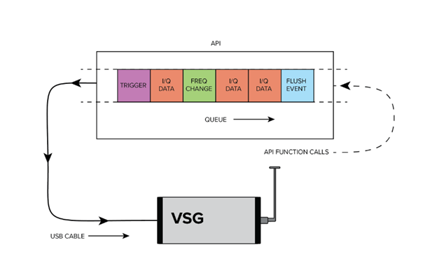
For long waveform generation or for transmitting a complex sequence of events such as frequency hopping or triggers, a collection of functions are available in the API which allow a user to buffer a sequence of configuration and transmit events.
For a list of all examples, please see the examples/ folder in the SDK.
The following functions can be buffered/queued:
Roughly 1/5th of a second of I/Q data can be buffered. If the buffer is full and vsgSubmitIQ data is called, the function blocks until space is available in the buffer.
Flushing the queue via the vsgFlush or vsgFlushAndWait functions are recommended to properly execute trailing commands in the queue.
It is the users responsibility to ensure events are queued quickly enough to execute them in a deterministic (packed) manner.
Queued commands are "batched", meaning they are sent to the device as groups of commands. When starting a new queue, early commands in the queue will not be sent to the device until a "batch" has been accumulated. If enough time passes between queued commands (10's of milliseconds), the current batch of commands will be sent to the device anyways. This may result in undesirable behavior if the expectation is deterministic control/output.
Calling vsgAbort will cause all I/Q data in the buffer to be dumped and any pending frequency/level changes to be completed in the order received.
Frequency hopping is achieved through the Complex Signal Generation (Streaming) interface. Changing frequency via the vsgSetFrequency function takes a deterministic amount of time which is device dependent,
Waveforms are provided to the API as I/Q samples. I/Q samples should be provided as contiguous interleaved real and imaginary pairs.
Example: [re1, im1, re2, im2, …, reN, imN] would be an array of N I/Q samples, which would equal 2 * N contiguous floating-point values.
Each {re, im} pair represents a single sample. Each real and imaginary value should be a 32-bit floating point value. I/Q samples are provided in full scale. An I/Q magnitude equal to 1.0 will transmit at the output level set by the user.
Magnitude of I/Q sample is calculated as sqrt(I2 + Q2)
To measure the output power of a sample in dBm, use the formula:
Power of I/Q sample = Output power set in vsgSetLevel + 20 * log10(magnitude of I/Q sample)
Internally I/Q samples are scaled to achieve the user-selected output power. The default scaling is 0.5 and increases/decreases around this value to digitally scale where the internal amplifier and attenuator cannot. The internal scale can be queried through the API. Because we use a base scale of 0.5, this means magnitudes greater than 1.0 can be tolerated. Clipping occurs when either I or Q value exceeds 1.0 post scaling. The scaling is performed as such.
Scaled I/Q = { real * scaleFactor, imag * scaleFactor }
If you have a waveform with amplitudes much greater than 1.0, it is recommended to query the scale to verify clipping won’t occur or scale the entire waveform and adjust the output power to compensate.
Triggers can be output on the dedicated RF trigger connector on the VSG. They can be synchronized with the RF output through the Complex Signal Generation (Streaming) interface, specifically the vsgSubmitTrigger function. Calling vsgSubmitTrigger inserts a trigger event into the queue. For example, a call sequence of,
Would cause a trigger event to occur on the first sample of the data provided to the second vsgSubmitIQ function.
All triggers are rising edge only. The trigger will stay high for the duration specified by the vsgSetTriggerLength function. Triggering again before the trigger level has fallen will keep the trigger high, and you will not see another rising edge.
While there is a not a hard limit, up to several thousand triggers per second have been tested. Max trigger rates are tied to CPU performance, and on lower power PCs, less than this may be achievable.
The VSG200 supports a low frequency output path between 100kHz - 17.5MHz. There are several limitations in this path that are enumerated in the product manual. Some of them are enumerated here,
The API is not thread safe. A multi-threaded application is free to call the API from any number of threads if the function calls are synchronized (i.e. using a mutex). Not synchronizing your function calls will lead to undefined behavior.
The API can manage multiple devices within one process. In each process the API manages a list of open devices to prevent a process from opening a device more than once. You may open multiple devices by specifying the serial number of the device directly or allowing the API to discover them automatically.
If you wish to use the API in multiple processes, it is the user’s responsibility to manage a list of devices to prevent the possibility of opening a device twice from two different processes. Two processes communicating to the same device will result in undefined behavior. One possible way to manage inter-process information is to use a named mutex on a Windows system.
If you wish to interface multiple devices on Linux, see Multiple Devices.
All functions return a VsgStatus error code. VsgStatus is an enumerated type representing the success of a given function call. The integer values associated with each status provides information about whether a function call succeeded or failed.
An integer value of zero indicates no error or warnings. Negative integer status values indicate errors and positive values represent warnings.
A descriptive string of each status type can be retrieved using the vsgGetErrorString function.
All functions other than initialization functions take a device handle as the first parameters. This integer is obtained after opening the device through either the vsgOpenDevice or vsgOpenDeviceBySerial function. This handle uniquely identifies the receiver for the duration of the application execution, or until vsgCloseDevice is called.
Each function returns an error code which can provide warnings or errors related to the execution of the function. There are many cases where you will need to monitor these codes to determine the success or failure of an operation. See a list of common error codes and their descriptions in the Appendix.
By default, Linux applications cannot increase the priority of individual threads unless ran with elevated privilege (root). On Windows this issue does not exist, and the API will elevate the USB data acquisition threads to a higher priority to ensure USB data loss does not occur. On Linux, the user will need to run their application as root to ensure USB data acquisition is performed at a higher priority.
If this is not done, there is a higher risk of USB data loss.
In our testing, if little additional processing is occurring outside the API, 1 or 2 devices typically will not experience data loss due to this issue. Once the user application increases the processing load or starts performing I/O such as storing data to disk, the occurrence of USB data loss increases and the need to run the application as root increases.
There are limitations that apply when attempting to use multiple devices on Linux. The maximum amount of memory that can be allocated for USB transfers on Linux is 16MB. A single VSG can stay within this limitation, but two devices will exceed this limitation and can cause the API to crash when you do. The USB allocation limit can be changed by writing to the file
/sys/module/usbcore/parameters/usbfs_memory_mb
A good value would be N * 16 where N is the number of devices you plan on interfacing.
One way to write to this file is with the command
where 32 can be replaced with any value you wish.
The API is C compatible which ensures it is possible to interface the API in most languages that can call C functions. These languages include C++, C#, Python, MATLAB, LabVIEW, Java, etc. Some examples of calling the API in these other languages are included in the code examples folder.
The API consists of several enumerated(enum) types, which are often used as parameters. These values can be treated as 32-bit integers when callings the API functions from other programming languages. You will need to match the enumerated values defined in the API header file.
Newer CPU models implement efficient power saving techniques that can interfere with and reduce USB bandwidth. If you are using one of these CPU models, you can experience issues when using the API which might appear as data loss or signal drop outs when inspecting the RF output of the VSG.
There are 2 potential solutions to this problem:
1) Enable the power saving CPU mode through the API. This has the effect of adding an artificial load to the API to keep the CPU from entering any low power CPU states that might affect the USB throughput. You will see an increase in CPU usage through this method.
2) Disable “C-States” in the BIOS of the PC. This prevents the OS from being able to put the CPU in these low power states which affect USB performance. This will increase power consumption of the PC which will affect battery life but will see lower CPU usage (since power saving CPU mode can be disabled).
The default state of this mode is disabled in the API.
PCs most affected are laptops and ultraportable devices running Windows.
Versions are of the form major.minor.revision.
A major change signifies a significant change in functionality relating to one or more measurements, or the addition of significant functionality. Function prototypes have likely changed.
A minor change signifies additions that may improve existing functionality or fix major bugs but makes no changes that might affect existing user’s measurements. Function prototypes can change but do not change existing parameters meanings.
A revision change signifies minor changes or bug fixes. Function prototypes will not change. Users should be able to update by simply replacing DLL.
Version 1.0.0 – Official release
For technical questions, email support@signalhound.com.
For sales questions, email sales@signalhound.com.