|
PCR4200 API
|
|
PCR4200 API
|
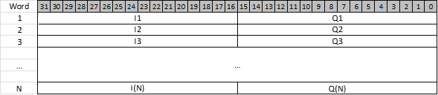
Each channel on the PCR4200 is assigned a unique stream identifier, and is treated as an independent, time-aligned, VITA 49 stream. The PCR4200 uses Signal Data packets and Context packets. Both types contain headers with metadata which includes a Stream Identifier and timestamp.
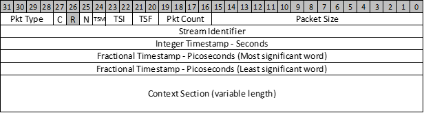
Signal Data packets encapsulate fixed-sized 8192 byte blocks of 2048 IQ data samples, along with a 32-bit trailer to convey additional critical information about the state of the receiver at the time the samples were obtained. For example, if the system was being overdriven this would be reported by an indicator in the trailer.
Context packets contain information about the receiver’s settings. The PCR4200 uses a fixed packet size using a predefined set of 10 fields.
The stream identifier is a 32-bit number assigned to this VRT packet stream. All packets with this ID belong to the same stream. The default stream identifier is set to the channel number.
When the Integer-seconds timestamp conveys Coordinated Universal Time (UTC) it shall provide the reference point time of the first data sample in the packet in seconds since midnight January 1, 1970, Greenwich Mean Time.
The real-time timestamp extends the resolution of the Integer-seconds timestamp down to one picosecond. It accomplishes this by conveying the reference-point time of the first data sample in the Signal Data packet in picoseconds, relative to the time of the last Integer-seconds timestamp increment. The PCR4200 timestamp has a 4 nanosecond resolution.
The IF Data Payload format for the Signal Data packet will be 16-bit signed integers representing complex Cartesian samples, or I/Q samples. Each I/Q data sample is a signed two’s complement 16-bit value, ranging from -32768 to +32767. A PCR4200 Signal Data packet contains 2048 I/Q samples.
For a description of external triggers, please see External Triggering.
When high rate triggering is enabled, the least significant bit in the In-phase data I[0] is replaced with (trigger logic level XOR’ed with bit Q[0]). The logic level of the trigger for each I/Q sample can then be obtained by using the XOR operation on the least significant bits of the I and Q data. This whitens the trivial amount of noise we add, removing the need to mask these bits. Triggers are delayed by the I/Q processing delay, such that they are aligned in the data. The trailer’s bit 8 will be set if a trigger level change occurs in the packet.

Enable bits 31, 30, 29, 25, 21, 20 are set, indicating Calibrated Time, Valid Data, Reference Lock, ADC Over-range, and both user-defined bits are used. The user-defined bits are used for DDR buffer full and trigger detected, respectively. The values for these bits are offset 12 bits lower.
Context packets are sent periodically. The interval is set when setting up the streaming channels. The context packets will cycle through the active channels, as many setups will use different settings per channel.
Time stamps for context packets will be the internal clock time unless an event, such as a frequency change, occurs. For context packets indicating an event, the time stamp will correspond to the time of the event.
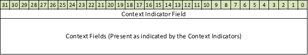
The Context Section is a variable size field which contains a number of additional fields based on the contents of the Context Indicator Field. The Context Indicator Field is the first word in the Context Section and will always be present. This and all fields used by Signal Hound are discussed below.
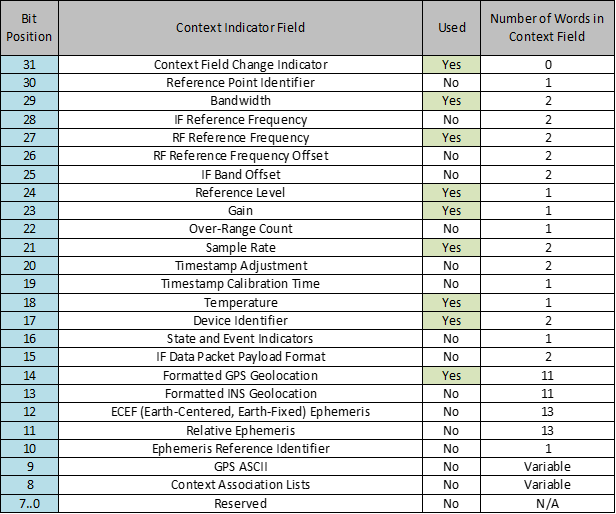
Only the fields that are marked used will be present in the Context packets and defined in this document.
This bit is set to one when at least one Context Field contains a new value. If the Context Fields have not changed, the Context Field Change Indicator will be set to zero.
The bandwidth field describes the amount of usable spectrum of the associated Signal Data Stream. The bandwidth is described by Signal Hound as the width in Hertz between the two cutoff frequencies of the IF bandpass filter. The cutoff frequencies are defined as the 3dB point, where the filter is attenuating the signal by 3dB. This value will always be smaller than the sample rate as the Signal Hound device always ensures the filter has sufficient amplitude roll off to prevent aliasing.
The value of the bandwidth field is expressed in Hertz and is in the 44.20 fixed point format as shown below.

The RF reference frequency field provides the original frequency the input was translated by to produce the IF data. This frequency is usually the frequency requested through device configuration. The RF reference frequency follows the format explained in the Frequency Format section.
The reference level field provides a power level that is used to calculate the magnitude of the received data. See Calculating I/Q Data Magnitude for an equation for this.
The reference level format is a 16-bit fixed point value of the format 9.7 as shown below.

The gain/attenuation field describes the amount of attenuation the signal undergoes in the system, expressed in dB.
The attenuation values are formatted as shown below. Two 16-bit gain values in a 9.7 fixed point format are packed into one word.

The sample rate field expresses the sample rate of the data samples in the paired Signal Data packet. The value of the field is expressed in Hertz and follows the format described in the Frequency Format section.
The temperature field provides the internal operating temperature of the device. The temperature field is a 16-bit fixed point value expressed in Celsius units.
For best accuracy and image rejection, check that the temperature is within 2°C of when the stream started. If not, a recalibration cycle is recommended.
The fixed-point format is 10 integer bits and 6 fractional bits. The format is as shown below.

The device identifier field is used to identify the manufacturer and model of the device generating the Context Packet Stream.
The Manufacturer OUI field will be set to FF-FF-FF.
The Device code field will be set to 0x7000:

The GPS geolocation context field format is displayed below:
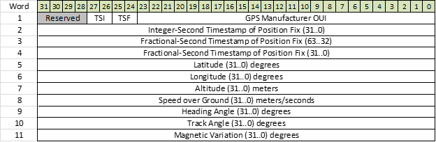
The GPS geolocation field is parsed from the internal U-BLOX GPS. The PCR-4200 uses all fields except magnetic variation.
The format used for the angle values represented in the GPS geolocation field are 32 bit fixed point values of the format 10.22 as shown below.

The Latitude subfield uses the angle format described and ranges from -90 (South) to +90 (North) degrees.
The Longitude subfield uses the angle format described and ranges from -180.0 (West) to +180.0 (East) degrees.
The Altitude format is a 32-bit fixed point value of the format 27.5 as shown below. The altitude format has a range of +-67108 km and a resolution of 3.1 centimeters.

A number of frequencies are of the format shown in the following figure. The frequency is stored as a 64-bit fixed point number of the format 44.20, that is, an integer value represented in 44 bits, and a fractional value in 20 bits. This allows a frequency range of +/- 8.79 THz and a resolution of 0.95 μHz. The 64-bit value is split between two words, where the most significant word comes first.

The I/Q data sent in the V49 data packets is provided as full scale. It can be converted to corrected I/Q (scale to mW) using the equations provided in Converting From Full Scale to Corrected I/Q. The correction factor that should be used for V49 data is
correction = pow(10.0, refLevel / 10.0)
where refLevel is from the Reference Level field in the context packet, and is provided as dBm.