|
PCR4200 API
|
|
PCR4200 API
|
This documentation is a reference for the Signal Hound PCR4200 (PCR) programming interface (API). The API provides a set of C functions for making measurements with the PCR device. The API is C ABI compatible making is possible to be interfaced from many programming languages.
All code examples are located in the examples/ folder in the SDK which can be downloaded at www.signalhound.com/software-development-kit.
Versions are of the form major.minor.revision.
A major change signifies a significant change in functionality relating to one or more measurements, or the addition of significant functionality. Function prototypes have likely changed.
A minor change signifies additions that may improve existing functionality or fix major bugs but make no changes that might affect existing user’s measurements. Function prototypes can change but do not change existing parameters meanings.
A revision change signifies minor changes or bug fixes. Function prototypes will not change. Users should be able to update by simply replacing the .DLL/.so.
The PCR4200 has 4 configurable reciever channels. These channels can be configured as I/Q streaming channels up to 50MS/s. Each channel can be configured to a different frequency using an independent LO, or use a common shared LO for phase coherent operation. In addition, up to 1 channel can be configured as a sweeping channel, with a sweep speed up to ~250GHz/s, with full control over sweep configuration parameters.
The channel configuration must be set up front and cannot be changed while the measurements are active. Channel configuration is set with the pcrSetChannelConfig function.
Some example channel configurations are,
If the device is configured for both sweeps and I/Q streaming, these 2 operations can happen simultaneously and independently of each other. To achieve optimal performance it will be necessary to use multi-threading to sweep and stream simultaneously.
The PCR4200 operates over a single 10GbE link. Both control and data are sent over the link.
Control and sweep data occurs over a network socket targetting the main device network configuration (IP addr + port).
Local I/Q streaming occurs over a separate network socket using the same IP addr with a custom port. By default the local I/Q streaming port is 4991 (standard VRT port). Both the device network configuration and the local I/Q streaming port are configurable. See the pcrNetworkConfig** functions for configuring the PCR network settings and the pcrSetStreamLocalAddr for setting the local streaming mode port.
If the device is configured for Vita49 Streaming Mode, a full destination IP addr and port are provided as the destination address for the Vita49 data. See pcrSetStreamVrtAddr.
One use case for Vita49 streaming, is configuring the PCR4200 via one PC with a different PC receiving the Vita49 data. This can be accomplished through a network switch and proper network configuration.
Any application using the PCR4200 API will follow these steps to interact and perform measurements on the device.
1. Open the device and receive a handle to the device resources.
Opening a device is done with the pcrConnectDevice function. This function will perform the full initialization of the device and if successful will return an integer handle which can be used for all future API function calls.
2. Configure the device.
At this point, you must configure the device for the desired measurement. All configuration of the PCR must be done up front prior to starting the measurement. Most settings cannot be changed once initated. It is also in this step that you "initiate" or "start" the measurements.
3. Acquire measurements.
Once the measurements have been configured and initiated, you can begin acquiring measurement data. Depending on the configuration, you will acquire sweep and I/Q data. Sweep and I/Q data can be acquired in parallel and it may be necessary to use multi-threading to achieve maximum throughput in this configuration. Also see Thread Safety.
4. Stop acquisitions, abort the current operation.
When you are done with the measurements, or you want to change the measurement configuration, you must first call the pcrAbort function. This stops the current measurements and puts the device in an idle mode ready to accept a new measurement configuration.
5. Close the device.
When you are done with the device, you will call pcrCloseDevice. This frees up all resources associated with the device and allows it to be reopened.
It is possible to open and close a device multiple times during the execution of a program.
6. Recalibration (Optional)
Recalibration is performed each time the device is reconfigured for a new measurement , using the pcrInitiate function. The recalibration process includes calculating correction coefficients using the devices current internal temperature. If the device temeprature drifts after this recalibration procedure, then measurement error due to temperature drift can occur.
If it recommended to reconfigure the device periodically when large temperature drifts occur. The device temperature can be monitored using the pcrGetDeviceDiagnostics and pcrGetFullDeviceDiagnostics functions.
Each channel of the PCR can be configured to stream I/Q data. All channels that are streaming I/Q data use the following shared settings
If the channel is configured to use the independent LO, then the frequency of each I/Q stream can be configured independently using the pcrSetChannelFreq function.
The phase relationship between channels remains stable when using the shared LO. This relationship persists between opening and closing the device, device reconfiguration, and power cycles. The phase relationship is affected by frequency and temperature. It will also naturally drift over time. It is recommended to recalculate and adjust the phase offsets/delays when changing frequency, the device experiences large temperature drift, or over time.
The API has some functions that assist with correcting for residual phase offset and delay, pcrSetChannelPhaseOffset and pcrSetChannelDelay. We provide an example of measuring the channel offsets and delays and applying them with these functions in the API.
All channels configured for both I/Q streaming and to use the shared LO use the frequency configured in the pcrSetSharedFreq function.
See the PCR product manual for phase drift typical plots for several common system scenarios.
See Phase Offset and Delay Calibration for more information.
There are 2 different modes in which the receiver can stream I/Q data.
The streaming mode is set with pcrSetStreamMode.
In the local streaming mode the API both configures the device and manages all I/Q data returned from the instrument. I/Q data is retrieved by the user using the pcrStreamRecv function.
The API buffers all I/Q data from the receiver into a circular buffer that stores about 1/4 of a second of data at the full 50MS/s sample rate. The pcrStreamRecv function polls the buffer and returns the requested number of I/Q samples. It is the responsibility of the user’s application to poll the I/Q data fast enough that data loss does not occur.
In the Vita49 streaming mode, the API only configures the device, and all I/Q data is streamed in the Vita49 format to a destination IP address and port. This has several potential benefits,
A description of the Vita49 data format can be found here. PCR4200 Vita49 Data Format.
The table below outlines the available I/Q sample rates for the PCR4200. Decimations > 1 are achieved using decimation (filtering + downsampling). This processing is performed either on the PCR or on the PC depending on sample rate. Processing performed on the PC will contribute to increased CPU load.
| Decimation | Sample Rate(MS/s) | Max Bandwidth(MHz) | Processing | Available Mode |
|---|---|---|---|---|
| 1 | 50 | 40 | PCR | Local + Vita49 |
| 2 | 25 | 20 | PCR | Local + Vita49 |
| 4 | 12.5 | 10 | PCR | Local + Vita49 |
| N = {8,16,....,256} | 50/N | 40/N | PCR + PC | Local Only |
Bandwidth is selected by the user, with a maximum value dependent on sample rate, and a minimum value functionally decided by the size of the filter being used. An arbitrarily small bandwidth can be selected, but a large filter rolloff at the higher samples rates conflicts with that goal.
The table also illustrates that only specific sample rates are available when in Vita49 streaming mode.
When streaming I/Q data through the API (local mode), the data can be returned either as 32-bit complex floats or 16-bit complex shorts depending on the data type set in pcrSetStreamDataType. 16-bit shorts are more memory efficient by a factor of 2 but require more effort to convert to absolute amplitudes and may be less convenient to work with.
When data is returned as 32-bit complex floats, the data is scaled to mW and the amplitude can be calculated by the following equation
Sample Power (dBm) = 10.0 * log10(re*re + im*im);
Where re and im are the real and imaginary components of a single I/Q sample.
When data is returned as 16-bit complex shorts, the data is full scale and a correction must be applied before you can measure mW or dBm. Values range from [-32768 to +32767]. To measure the power of a sample using the complex short data type, three steps are required.
float re32f = ((float)re16s / 32768.0);float im32f = ((float)im16s / 32768.0);re32f *= correction;im32f *= correction;Sample Power (dBm) = 10.0 * log10(re32f*re32f + im32f*im32f);The PCR4200 supports external trigger position information. This allows for high precision synchronization between multiple receivers and external equipment.
The TRIG In port on the PCR can detect a rising or falling edge (selected with pcrSetStreamTriggerEdge) and indicate which I/Q sample the edge occurred on. This sample indication can be provided for every individual I/Q sample. The mechanisms for retrieving the position information depend on what streaming mode is selected.
In local mode, trigger positioning is provided through the triggers buffer in the pcrStreamRecv function.
In Vita49 mode, triggering information is embedded into the Vita49 packet in a non-standard method described by High Rate Trigger.
This functionality is only supported in API versions 1.0.3 or newer combined with FW version 4.4.6 or newer.
The standard method of retuning is to stop the receiver with pcrAbort, update the receiver configuration, then restart the measurement with pcrInitiate. While being simple to implement, this method might be too slow for certain applications or might interrupt active measurements. The typical retune time of this method is ~30-40ms.
The PCR supports fast retuning of I/Q streaming channels through the use of the functions, pcrUpdateChannelShared, pcrUpdateChannelFreq, and pcrUpdateSharedFreq. These functions provide the ability to change specific I/Q streaming parameters while the device is actively streaming.
Notes on their use,
These methods work for both local and Vita49 streaming modes.
One use case for fast retuning is to implement search/handoff capability. A receiver can have 1 sweeping channel and several streaming channels. A processing loop might look like this,
1) Configure receiver and start measurement. 2) Perform sweep. 3) Look for signals of interest in sweep. If present, retune one or more streaming channels to view the signals of interest. 4) Perform next sweep while simultaneously streaming the signal(s) of interest. 5) Repeat
For direction of arrival and beamforming applications, the phase relationship and delays between multiple phase coherent channels must be known and calibrated out. While the PCR4200 and API do not have automatic phase offset and delay calibration, we provide functions for applying measured offsets and examples for measuring these error terms.
The PCR4200 contains an on board 20GHz vector signal generator. This can be used as a phase coherent input to all channels to assist with measuring these error terms. Once measured, the pcrSetChannelPhaseOffset and pcrSetChannelDelay functions provide automatic application of these values.
Phase offset is the direct phase offset measured between 2 phase coherent channels. For a 4 channel system, a common approach is to measure the phase offset of all channels referenced to channel 1, and apply the negative of the offset using the pcrSetChannelPhaseOffset function.
Delay is the time difference of arrival of a signal between 2 channels. As with phase offset, delay is often compared to channel 1 and applied using the pcrSetChannelDelay function. Delay corrects for the difference in lengths between RF paths between 2 channels. This difference in length can come from antennas, cables, connectors, and the PCR4200 itself (PCR trace lengths + parts).
See the SDK for phase offset and delay compensation examples.
See Phase Coherence and the Shared LO for more information.
The phase offset and delays are sensitive to temperature. The PCR4200 product manual shows typical plots of phase drift over time and temperature.
For optimal performance, the PCR should be actively measuring prior to calibrating offsets and delays. This ensures all hardware associated with the desired measurement is fully warmed up before measuring channel offsets.
One channel on the PCR4200 can function as a sweep channel. Sweeping represents the common spectrum analyzer measurement of plotting amplitude over frequency. Sweeps can be performed in parallel with I/Q streaming.
Only 1 sweep configuration can be active at a time.
Changing the sweep configuration requires reconfiguring the device. Reconfiguration involves stopping any I/Q streams.
All sweeps must be finished before you can reconfigure the device for a new sweep configuration.
Only linear spaced sweeps can be performed.
A sweep is returned from the API as a 1-dimensional array of measurement values. Each element in the array corresponds to a specific frequency. The frequency of any given element can be calculated as
Frequency of N'th element in sweep = StartFreq + N * BinSize
where StartFreq and BinSize are reported in the pcrSweepGetParameters function.
The measurement values can be returned in dBm or mV units.
The pcrGetSweep function is a blocking function which waits until the sweep completes to return. For large sweeps, blocking until complete may not be desireable. In that scenario you can take advantage of the asychronous functions pcrSweepStart and pcrSweepFinish.
Synchronous and asynchronous sweeps should not be mixed.
The PCR4200 includes a configurable vector signal generator (VSG), used to assist with phase offset and delay calibrations and basic general purpose use.
The VSG operates on the shared LO. The carrier frequency is configured with the pcrSetSharedFreq function. The output frequency can be utilized anywhere in the 20GHz frequency range of the instrument. The VSG has 40MHz bandwidth and a configurable I/Q pattern memory buffer.
Some VSG considerations,
There are two ways to control the sensitivity of the receiver, through the reference level or the attenuator. The reference level and attenuator can be set independently for both sweeps and streams. (pcrSetSweepRefLevel, pcrSetSweepAtten, pcrSetStreamRefLevel, pcrSetStreamAtten)
The reference level setting will adjust the sensitivity to have the most dynamic range for signals at or near (~5dB) below the reference level. If you know the expected input signal level of your signal, setting the reference level to 5dB above your expected input will provide the most dynamic range. Using the reference level, you can also ensure the receiver does not experience an ADC overload by setting a reference level well above input signal level ranges.
Setting the attenuator provides direct control of the sensitivity. If the attenuator is set to auto, then the API chooses the best attenuator value based on the reference level selected. The attenuator is set to auto by default.
Setting the reference level is the recommended way to control the sensitivity of the receiver.
The PCR4200 contains an internal GPS module (u-blox F9). This module has several functions,
The provided GPS antenna should be connected to the appropriate RF port on the PCR and GPS lock must be achieved to provide the functionality listed above.
The GPS can be in one of three states,
The current GPS state can be queried with pcrGetGPSState. If the device is actively making measurements the recommended way to wait for lock/discipline is by querying the GPS state after each measurement. If the device is idle (after an pcrAbort) the recommended method is to query the GPS state in a busy loop, preferably with a small wait (~1 second) between queries.
The GPS will automatically lock when the GPS antenna is connected. You can query the state of the GPS with the pcrGetGPSState function. The pcrGetGPSState function may be queried in a loop if waiting for lock.
From a cold start or after power cycle, the GPS lock may take several minutes to achieve. If you do not see a lock after several minutes, you might need to reposition the antenna. The antenna is expected to have clear access to sky. Once warm, lock can be achieved much quicker.
GPS lock is required for both high precision timestamps and geolocation.
The PCR4200 supports I/Q timestamping using both the internal and external GPS devices. This section covers the several methods by which I/Q timestamping can be performed.
This method of I/Q timestamping is the simplest and requires no external equipment. It's accuracy is dependent on the internal GPS performance.
When the internal GPS is locked, I/Q timestamping using the internal GPS occurs automatically. When using the API to stream I/Q data, timestamps are provided through the pcrStreamRecv function. Both the local and Vita49 I/Q data is timestamped.
Note: Until the GPS is locked, timestamping occurs using the system clock. Accuracy of the timestamps is unspecified.
If the GPS loses lock, the timestamps will advance at the nominal (system clock) rate until the GPS achieves lock again. Off GPS lock, timestamps will be coherent between measurement reconfigurations until the device is closed through the API or the device loses power.
It is recommended to enable GPS disciplining to increase the accuracy of the timestamps. See GPS Disciplining.
If the accuracy of the internal GPS is not adequate, or if you want to timestamp multiple PCR devices on a single GPS, an external GPS can be used to perform I/Q timestamping.
There are two approaches to performing timestamping using an external GPS, a manual and an automatic method. Both approaches require the external GPS to be connected to the PCR via,
Manual Approach
The manual approach monitors the PPS as a trigger position in the I/Q data stream and then uses the position to perform timestamping. Trigger positions can be monitored in both local I/Q streaming and V49 streaming using the high rate trigger data.
In the manual approach, the customer is responsible for corresponding trigger positions to the current second and extrapolating the timestamps between these trigger positions.
Automatic Approach
The automatic approach requires some up front configuration, but once configured the timestamp is calculated using the external PPS automatically for the user. In this approach, timestamps are provided through the normal methods, either through the timestamp parameter in pcrStreamRecv or embedded in the V49 data.
To configure the receiver for this approach, follow these steps,
The time will need to be set each time the I/Q stream is restarted. A race condition can occur where the PPS arrives after calling the pcrSetTime function but before the new time has arrived on the firmware. For this reason, it is recommended to call pcrSetTime early in the second interval.
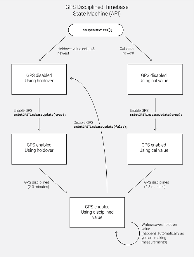
GPS disciplining is an advanced GPS lock state that must be enabled by the API user.
GPS disciplining provides 2 distinct improvements,
While GPS lock happens automatically, GPS discipline requires additional configuration. To enable GPS disciplining, use the pcrSetGPSTimebaseUpdate function. To summarize, the timebase is adjusted by the newer of the two correction factors, either the last GPS holdover value or the last Signal Hound calibration value. Only after enabling the GPS disciplining will the PCR utilize a GPS lock to discipline the SM and store holdover values.
When enabled, the API will instruct the receiver to use the internal GPS PPS to discipline the 10MHz internal timebase. This disciplining process adjusts a tuning voltage which the API will then store on the PC filesystem. This stored tuning voltage will then be used by the API in the future to tune the timebase. This allows the receiver to reuse a good GPS frequency lock even when no GPS antenna is attached.
Note: The stored GPS tuning voltage will override the tuning voltage created during calibration, and in almost all cases this is preferred as the latest GPS discipline will be the best frequency tune.
The GPS tuning voltage is stored in the ProgramData/ folder at
C:\ProgramData\SignalHound\cal_files\pcr########gps.bin
where the # is the device serial number. Delete this file to have the API revert to using the internally stored frequency calibration.
Using the API, customers can write custom messages to the internal u-blox F9 GPS receiver using the pcrWriteMessageToGPS function.
See the C++ examples for a full example of sending a message.
The Key and Value pairs used for configuring the GPS via pcrWriteMessageToGPS function can be found in the manual below under the Configuration Interface section.
Some commonly used key value pairs include the following
CFG-NAVSPG-DYNMODEL : Dynamic platform model., By default the GPS is configured to be stationay which is a value of 2. Many customers want to use one of the mobile models.
pcrWriteMessageToGPS(handle, 0x20110021, 0, 1); // Set GPS to Portable
pcrWriteMessageToGPS(handle, 0x20110021, 6, 1); // Set GPS to Airborn
CFG-BDS-USE_GEO_PRN : Use BeiDou geostationary satellites (PRN 1-5and 59 - 63)
pcrWriteMessageToGPS(handle, 0x10340014, 0, 1); // Don't use BeiDou satellites
CFG-NAVSPG-FIXMODE : Position fix mode pcrWriteMessageToGPS(handle, 0x20110011, 1, 1); // 2D Fix only
The fan can be controlled using the pcrSetFanEnabled and pcrSetFanSetPoint functions. When fans are enabled, the set point is the target device temperature that is maintained by the fan module. A set point either too high or too low can result in a fan that is always on or off.
If 100% fan speed is desired, enable the fans and set the setpoint to the minimum value, as specified by PCR_MIN_FAN_SETPOINT.
The PCR can enter a lower power state using the pcrSetLowPowerState function. The device must be idle (by calling pcrAbort) before calling this function. The low power state consumes ~30W of power compared to the 37-48W when active. No special procedure is required to leave the low power state, simply configure the receiver for your next measurement and call pcrInitiate. The PCR will not automatically re-enter the low power mode after coming back to idle after calling pcrAbort.
Multiple PCR4200s may be paired together to form a single higher channel count system. The API currently supports this functionality through the pcrPairDevice function. Through this function, one can create 4, 8, 12, and 16 channel count systems. This allows for configurations such as,
Multi-receiver considerations,
To connect 2 PCR devices in a multi-receiver configuration, these steps must be performed prior to interfacing the devices in the API.
The system is now ready for use.
When no longer using the devices in a multi-receiver operation, disconnect all RF cables described in the steps above, and replace the 50 Ohm terminator on the LO Out port on the primary receiver.
The API should only be considered thread safe when acquiring measurement data. For instance, opening, configuring and initiating the measurement should be performed in a single thread. Once the measurements have started, you can query I/Q and sweep data from separate threads. When you are finished, both the abort and close device functions should be performed in a single thread again.
The API can manage multiple devices within one process. In each process the API manages a list of open devices to prevent a process from opening a device more than once. You may open multiple devices by specifying the serial number of the device directly or allowing the API to discover them automatically.
If you wish to use the API in multiple processes, it is the user’s responsibility to manage a list of devices to prevent the possibility of opening a device twice from two different processes. Two processes communicating to the same device will result in undefined behavior. One possible way to manage inter-process information is to use a named mutex on a Windows system.
By default, Linux applications cannot increase the priority of individual threads unless ran with elevated privilege (root). On Windows this issue does not exist, and the API will elevate the data acquisition threads to a higher priority to ensure data loss does not occur. On Linux, the user will need to run their application as root to ensure data acquisition is performed at a higher priority. If this is not done, there is a higher risk of data loss.
For complete documentation on setting up a 10GbE network device, please refer to our network configuration manual,
https://signalhound.com/sigdownloads/SM200A/10GbE-Network-Configuration-Guide.pdf
The SDK includes an example setup script which configures the parameters discussed below.
MTU size must be set to 9000 to enable jumbo packets.
Receive side socket buffers must be large enough to account for the amount of data each device can keep in flight. While I/Q streaming, a PCR4200 device can keep up to ~32MB of data in flight. We recommend setting the maximum receive buffer size to 50MB.
We recommend setting the ring buffer sizes for tx and rx to 4096. This helps reduces packet loss in certain scenarios.
The API is C compatible which ensures it is possible to interface the API in most languages that can call C functions. These languages include C++, C#, Python, MATLAB, LabVIEW, Java, etc. Examples of calling the API in these other languages are included in the code examples folder.
The API consists of several enum types, which are often used as parameters. These values can be treated as 32-bit integers when callings the API functions from other programming languages. You will need to match the enumerated values defined in the API header file.
It is useful to understand the relationship between sweep parameters and sweep size. It is not possible to directly calculate the sweep size of a given configuration beforehand, but it is possible to estimate the sweep size to within a power of 2.
The equation that can be used to estimate sweep size is
Sweep Size (est.) = (Span * WindowBW) / RBW
Where span and RBW are specified in Hz, and window bandwidth is specified in bins. Window bandwidth is the noise bandwidth of the FFT window function used. See the Window Functions section for more information.
Below are the window functions used in the API. The API uses zero-padding to achieve the requested RBW so the noise bandwidth in this table should not be directly used.
| Window | NoiseBandwidth (bins) | Notes |
|---|---|---|
| Flat-Top | 3.77 | SRS flattop |
| Nuttall | 2.02 | None |
| Gaussian 6dB | 2.64 | σ = 0.1 |
For technical support, email support@signalhound.com.
For sales, email sales@signalhound.com.