|
SP API
|
|
SP API
|
This documentation is a reference for the Signal Hound SP145 (SP) spectrum analyzer programming interface (API). The API provides a set of C functions for making measurements with the SP devices. The API is C ABI compatible making is possible to be interfaced from most programming languages.
All code examples are located in the examples/ folder in the SDK which can be downloaded at www.signalhound.com/software-development-kit.
This section covers the main measurements available through the API.
Also see Basic API Usage for more information.
There are two ways to configure the sensitivity of the receiver, through the attenuator or the reference level.
(spSetAttenuator/spSetRefLevel) The spSetAttenuator function allows direct control of the attenuator. If the attenuator is set to auto, then the API chooses the best attenuator value based on the reference level selected. The attenuator is set to auto by default. It is recommended to leave the attenuator set to auto.
The reference level setting will automatically adjust the sensitivity to have the most dynamic range for signals at or near (~5dB) below the reference level. If you know the expected input signal level of your signal, setting the reference level to 5dB above your expected input will provide the most dynamic range for your measurement.
The reference level parameter is the suggested method of controlling the receiver sensitivity.
The SP145 has an internal GPS module which allows for positional data and high precision I/Q timestamping. For both position and time stamping, the GPS must acquire lock by connecting the provided GPS antenna. The GPS can also discipline the internal timebase of the SP145 enabling high precision frequency measurements and stable I/Q timestamping.
See spGetGPSInfo for retrieving position information.
The GPS will automatically lock with no external assistance. You can query the state of the GPS lock with either the spGetGPSState function, or by examining the return status of spGetGPSInfo. From a cold start, expect a lock within the first few minutes. A warm or hot start should see lock much quicker.
When the GPS is locked, I/Q data and sweep timestamping occurs using the internal GPS PPS signal and NMEA information. Once GPS lock is achieved, GPS timestamping occurs immediately and required no user intervention. Until the GPS is locked, timestamping occurs with the system clock.
If the GPS loses lock, the timestamps will advance at the nominal rate until the GPS achieves lock again. Off GPS lock timestamps will be coherent between measurement reconfigurations until the device is closed through the API or the device loses power.
It is recommended to enable GPS disciplining to ensure timestamps are accurate between internal PPS signals.
The system GPS can be in one of three states,
The current GPS state can be queried with spGetGPSState. If the device is actively making measurements the recommended way to wait for lock/discipline is by querying the GPS state after each measurement. If the device is idle (after an spAbort) the recommended method is to query the GPS state in a busy loop, preferably with a small wait between queries.
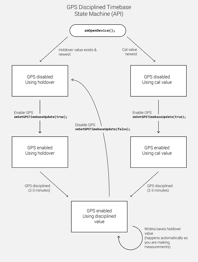
The GPS will lock automatically with a GPS antenna attached, but for the GPS to discipline the SP145, it must first be enabled. To enable GPS disciplining, use the spSetGPSTimebaseUpdate function. Below is the state machine for GPS disciplining. To summarize, the timebase is adjusted by the newer of the two correction factors, either the last GPS holdover value or the last Signal Hound calibration value. Only after enabling the GPS disciplining will the SP utilize a GPS lock to discipline the SP and store holdover values.
Using the API, customers can write custom messages to the internal u-blox M8 GPS receiver. The user can also retrieve responses to these messages. The two functions that enable this are spWriteToGPS (writing) and spGetGPSInfo (reading).
All messages sent to the GPS are sent over port 4 (SPI). This is the only port the customer has access to. UBX and NMEA messages can be sent. All messages are documented in the u-blox M8 GPS manual. Messages must match the frame structure documented in the u-blox manual. For example, to send a UBX message, the sync chars, class, ID, length, payload (if present), and 2-byte checksum must all be present and in the correct order in the provided message.
An example message for a “Get” UBX-CFG-NAV5 msg with empty payload is
msg[8] = {0xB5, 0x62, 0x06, 0x24, 0x0, 0x0, 0x2A, 0x84};
Responses are returned with the NMEA sentences through the spGetGPSInfo function. Responses must be parsed by the customer and can appear anywhere in the NMEA response buffer, including being split between buffers (rare).
To retrieve a response, call spGetGPSInfo with an adequately sized nmea buffer until the updated parameter is set to true, then parse the response for your message. The device requires GPS lock to receive a response message. It does not require GPS lock to send a message to the GPS.
See the C++ examples for a full example of sending and retrieving UBX messages.
A link to the u-blox M8 manual and protocol specification is below.
The SP145 has a GPIO port that can be configured for one of the following,
The GPIO output pin can be configured to automatically emit bytes via UART as the device sweeps across a specified frequency range. The frequency boundaries and bytes to be written are configured with spSetSweepGPIOSwitching.
This functionality is useful for controlling an antenna assembly (i.e. one of the Signal Hound RF switches) while very quickly sweeping a large frequency range. For instance, using the GPIO to switch between different antennas to be used for different frequencies as the SP sweeps the configured span. This would be much faster than individually sweeping each antenna manually.
Due to the digital nature of the SP device, there is a limit on the resolution on which the GPIO can change for GPIO sweeps. The frequency resolution at which the device will emit a new UART write is 30.72MHz.
This means the GPIO will not switch at the precise frequency you provide. The API is deterministic in choosing which frequencies to switch at, meaning, the same configuration will result in the same GPIO switch frequencies.
The API does not output or provide the actual frequencies the device switched the GPIO at. We recommend experimenting with your setup until you find an adequate configuration.
The SP has 2 power states, on and standby. Standby can be used to reduce power consumption. There is a ~50ms time penalty for switching from standby to on.
A short description of each power state is described below.
The SP API is not thread safe. A multi-threaded application is free to call the API from any number of threads if the function calls are synchronized (i.e. using a mutex). Not synchronizing your function calls will lead to undefined behavior.
The API can manage multiple devices within one process. In each process the API manages a list of open devices to prevent a process from opening a device more than once. You may open multiple devices by specifying the serial number of the device directly or allowing the API to discover them automatically.
If you wish to use the API in multiple processes, it is the user’s responsibility to manage a list of devices to prevent the possibility of opening a device twice from two different processes. Two processes communicating to the same device will result in undefined behavior. One possible way to manage inter-process information is to use a named mutex on a Windows system.
If you wish to interface multiple devices on Linux, see the Linux Notes.
By default, Linux applications cannot increase the priority of individual threads unless ran with elevated privilege (root). On Windows this issue does not exist, and the API will elevate the USB data acquisition threads to a higher priority to ensure USB data loss does not occur. On Linux, the user will need to run their application as root to ensure USB data acquisition is performed at a higher priority.
If this is not done, there is a higher risk of USB data loss for streaming modes such as I/Q, real-time, and fast sweep measurements on Linux.
In our testing, if little additional processing is occurring outside the API, 1 or 2 devices typically will not experience data loss due to this issue. Once the user application increases the processing load or starts performing I/O such as storing data to disk, the occurrence of USB data loss increases and the need to run the application as root increases.
There are system limitations when attempting to use multiple Signal Hound USB 3.0 devices* simultaneously on Linux operating systems. The default amount of memory allocated for USB transfers on Linux is 16MB. A single Signal Hound USB 3.0 device will stay within this allocation size, but two devices will exceed this limitation and can cause connection issues or will cause the software to crash.
The USB memory allocation size can be changed by writing to the file
/sys/module/usbcore/parameters/usbfs_memory_mb
A good value would be N * 16 where N is the number of devices you plan on interfacing simultaneously. One way to write to this file is with the command,
sudo sh -c ‘echo 32 > /sys/module/usbcore/parameters/usbfs_memory_mb’
where 32 can be replaced with any value you wish. You may need to restart the system for this change to take effect.
*Includes both Signal Hound USB 3.0 spectrum analyzers and signal generators.
The SP interface is C compatible which ensures it is possible to interface the API in most languages that can call C functions. These languages include C++, C#, Python, MATLAB, LabVIEW, Java, etc. Examples of calling the API in these other languages are included in the code examples folder.
The API consists of several enum types, which are often used as parameters. These values can be treated as 32-bit integers when callings the API functions from other programming languages. You will need to match the enumerated values defined in the API header file.
This project enables the user to retrieve sampled I/Q data and frequency sweeps from the SP receiver through a number of convenience functions written in Python. These functions serve as a mostly one-to-one binding to the native API, and perform the majority of C shared library interfacing necessary to communicate with the receiver.
Python 3 is required to use the Python interface functions. The API has been tested with Python 3.6.1 on Windows.
The Spike software must be fully installed before using the Python interface functions. Additionally, ensure the SP receiver is stable and functioning in Spike before using the Python interface.
Several SciPy and NumPy packages are required to use the Python interface functions, due to the need for fast array processing. The easiest way is to install the SciPy stack, available here: https://www.scipy.org/install.html. Alternatively, the necessary individual packages could be installed.
For our tests we used the 64-bit version of Anaconda for Windows.
Place sp_api.dll into the spdevice/ folder, along with sp_api.py.
To call the functions from outside the spdevice/ directory you may need to add the spdevice folder to the Python search path and to the system path. This can be done by editing PATH and PYTHONPATH in: Control Panel > System and Security > System > Advanced system settings > Advanced > Environment Variables > System variables.
Place sp_api.so into the spdevice/ folder, along with sp_api.py.
Edit the line in sp_api.py from
splib = CDLL("spdevice/sp_api.dll")
    to
splib = CDLL("spdevice/sp_api.so")
The functions under the "Public" heading are callable from external scripts. They are functionally equivalent to their C counterparts, except memory management is handled by the API instead of the user. Data is returned in Numpy arrays by the acquisition functions.
To run the example scripts, navigate to the folder containing the example .py files. Each example file is standalone and provides example code for calling the provided Python functions for the SP145.
This section describes I/Q measurement attributes.
The table below outlines the available I/Q sample rates and corresponding decimations for SP devices. See the software filter limitations in the following section for more information about filtering and bandwidth.
| Decimation | LTE Rate (USB 3.0) MS/s | Downsampling (All units) |
|---|---|---|
| 1 (Minimum) | 61.44 | None |
| 2 | 30.72 | Hardware only |
| 4 | 15.36 | Hardware only |
| 8 | 7.68 | Hardware only |
| 16 | 3.84 | Hardware/Software |
| N = {32, 64, …} | 61.44 / N | Hardware/Software |
| 4096 (Maximum) | 0.015 | Hardware/Software |
I/Q data can be returned either as 32-bit complex floats or 16-bit complex shorts depending on the data type set in spSetIQDataType. 16-bit shorts are more memory efficient by a factor of 2 but require more effort to convert to absolute amplitudes and may be less convenient to work with.
When data is returned as 32-bit complex floats, the data is scaled to mW and the amplitude can be calculated by the following equation
Sample Power (dBm) = 10.0 * log10(re*re + im*im);
Where re and im are the real and imaginary components of a single I/Q sample.
When data is returned as 16-bit complex shorts, the data is full scale and a correction must be applied before you can measure mW or dBm. Values range from [-32768 to +32767]. To measure the power of a sample using the complex short data type, three steps are required.
float re32f = ((float)re16s / 32768.0);float im32f = ((float)im16s / 32768.0);re32f *= correction;im32f *= correction;Sample Power (dBm) = 10.0 * log10(re32f*re32f + im32f*im32f);The user can enable a baseband software filter on the I/Q data with a selectable bandwidth. If the software filter is disabled, the signal will only have been filtered by the hardware as described below.
The hardware uses several half-band filters to accomplish decimations 2, 4, and 8 and there is non-negligible aliasing between 0.8 and 1.0 of the sample rates. Software filtering will eliminate this aliasing at the cost of a slightly smaller cutoff frequency.
Most users will want to enable the software IF filter for better rejection in the stop band, as well as the convenience of a selectable IF bandwidth. Users may forgo the software filter to reduce CPU load on the PC or if custom signal conditioning is performed.
Software filtering is enabled by default for decimations greater than 8.
The table below shows the maximum available bandwidth with the filter disabled and the maximum bandwidth allowed with the filter enabled. These numbers apply for both base samples rates.
| Decimation | Usable Bandwidth (MHz) Filter Disabled | Max Bandwidth (MHz) Filter Enabled |
|---|---|---|
| 1 | 41.5 | 41.5 |
| 2 | 20 | 19.2 |
| 4 | 10 | 9.6 |
| 8 | 5 | 4.8 |
| 16 | 2.5 | 2.4 |
| 32 | 1.25 | 1.2 |
| 64 | 0.625 | 0.6 |
| 128 | 0.3125 | 0.3 |
| 256 | 0.15625 | 0.15 |
| 512 | 0.078125 | 0.075 |
| 1024 | 0.039063 | 0.0375 |
| 2048 | 0.019531 | 0.01875 |
| 4096 | 0.009766 | 0.009375 |
It is useful to understand the relationship between sweep parameters and sweep size. It is not possible to directly calculate the sweep size of a given configuration beforehand, but it is possible to estimate the sweep size to within a power of 2.
The equation that can be used to estimate sweep size is
Sweep Size (est.) = (Span * WindowBW) / RBW
Where span and RBW are specified in Hz, and window bandwidth is specified in bins. Window bandwidth is the noise bandwidth of the FFT window function used. See the Window Functions section for more information.
Below are the window functions used in the API. The API uses zero-padding to achieve the requested RBW so the noise bandwidth in this table should not be directly used.
| Window | NoiseBandwidth (bins) | Notes |
|---|---|---|
| Flat-Top | 3.77 | SRS flattop |
| Nuttall | 2.02 | None |
| Kaiser | 1.79 | α = 3 |
| Blackman | 1.73 | α = 0.16 |
| Chebyshev | 1.94 | α = 5 |
| Hamming | 1.36 | α = 0.54, β = 0.46 |
| Gaussian6dB | 2.64 | σ = 0.1 |
When enabled, the API will instruct the receiver to use the internal GPS PPS to discipline the 10MHz internal timebase. This disciplining process adjusts a tuning voltage which the API will then store on the PC filesystem. This stored tuning voltage will then be used by the API in the future to tune the timebase. This allows the receiver to reuse a good GPS frequency lock even when no GPS antenna is attached.
Note: The stored GPS tuning voltage will override the tuning voltage created during calibration, and in almost all cases this is preferred as the latest GPS discipline will be the best frequency tune.
The GPS tuning voltage is stored in the ProgramData/ folder at
C:\ProgramData\SignalHound\cal_files\sp########gps.bin
where the # is the device serial number. Delete this file to have the API revert to using the internally stored frequency calibration.
Disable the automatic GPS timebase update to bypass this functionality with the spSetGPSTimebaseUpdate function.
For technical support, email support@signalhound.com.
For sales, email sales@signalhound.com.